 CacheGuard-OS
User's Guide - Version UF-2.5.2
The Network
A freshly installed CacheGuard-OS has no IP configurations at all and before being able to connect to it as an administrator (admin user), you must set an IP address for at least one of its network interfaces. The only way to set an IP address for the first time on a CacheGuard appliance is to use the CacheGuard appliance console port. At the first login (as the admin user) via the console port, a command named setup is automatically executed and allows you to set CacheGuard's internal and external IP addresses. As an alternative method, you can use the ip command.Network Interfaces
With a CacheGuard appliance, the network is divided into at least two zones: the internal zone and the external zone. The external zone is considered an untrusted zone (the Internet), while protected users and servers should be placed in the internal zone (considered trusted). A third optional zone called auxiliary can be created and used as per your convenience (for instance, as a DMZ or as a Back Office zone). The internal zone can optionally be divided into sub-zones using tagged VLANs.CacheGuard appliance connects each zone via a distinct logical network interface. Hence, a CacheGuard appliance can support up to three logical network interfaces: the external, the internal, and the auxiliary logical network interfaces. In this network topology, internal users and servers are routed via the internal interface, while the CacheGuard appliance uses its external interface to connect to the Internet.
A logical network interface should be associated with at least one physical network interface. The link command allows you to associate a logical network interface with a physical (eth0, eth1...) network interface. A link configuration in which more than one physical network interface is associated with a logical network interface is called link bonding. The link bonding is an active/backup link configuration that allows service continuity in the event of a link failure. You can refer to the Link Bonding section for further information on link bonding.
Appliance IP Addresses
To support the IP protocol, a logical network interface must be associated with a main IP address. The ip command allows you to set main IP addresses. Additional IP addresses can be implicitly associated with a logical network interface by other commands. For instance, the vrrp command allows you to create floating IP addresses in HA mode, while the rweb command may create IP aliases associated with a main IP address. The example below sets the external IP address to 192.168.1.1 255.255.255.0 and the internal IP address to 10.20.0.254 255.255.0.0:- ip external 192.168.1.1 255.255.255.0
- ip internal 10.20.0.254 255.255.0.0
- apply
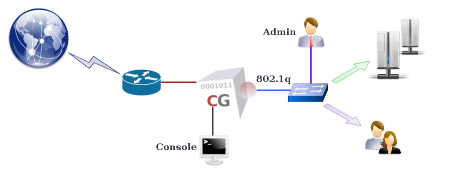
Using 802.1q VLANs
CacheGuard appliance supports 802.1q VLAN (Virtual LAN) tagging on its internal network interface to secure and isolate predefined functional traffic (admin, web, rweb...). When using tagged VLANs, a pseudo network interface is implicitly created for each defined VLAN. To use VLANs, you have to activate the VLAN mode by using the mode vlan on command and then configure VLANs with the help of the vlan and ip commands. Note that in VLAN mode, the native IP address associated with the internal network interface is no longer active, and you should configure a separate IP address for each pseudo network interface. For instance, the following commands define tagged VLANs 10, 20, and 30 respectively associated with the web, rweb, and admin functional traffic, and set a distinct IP address for each created VLAN (all other functional traffic will remain in the default VLAN 0).- vlan web 10
- vlan rweb 20
- vlan admin 30
- ip internal.0 10.0.0.254 255.255.255.0
- ip internal.10 10.0.10.254 255.255.255.0
- ip internal.20 10.0.20.254 255.255.255.0
- ip internal.30 10.0.30.254 255.255.255.0
- mode vlan on
- apply
Network Routes
To route (or forward) IP traffic, you must create routing tables. CacheGuard-OS supports static routes only. However, you have the possibility to create multi-gateway routes to balance the IP routing between multiple gateways. In a multi-gateway configuration, gateway failures can be detected and the routing configuration dynamically modified to avoid routing traffic via failed gateways. Please note that gateways in a route specification should be directly connected to a CacheGuard network interface and have an IP address in the same network as the connected network interface IP address. For example, the following commands allow you to create two default gateways via the 192.168.1.254 and 192.168.1.253 gateways and a static route to the 172.22.22.0 255.255.255.0 network via the 10.20.0.1 gateway.- ip route add default 192.168.1.254
- ip route add default 192.168.1.253
- ip route add 172.22.22.0 255.255.255.0 10.20.0.1
- apply
Domain Name Servers
To connect to external name-based services (for instance, websites), CacheGuard appliance needs a DNS (Domain Name Server) to translate domain names to IP addresses. CacheGuard appliance embeds a caching-only DNS (Domain Name Server) that you can activate by adding the localhost (or the 127.0.0.1 loopback IP address) to the list of DNS servers. You also have the possibility to add external DNS to the system using the dns command. If you activate the internal DNS server, you will have the possibility to allow external clients to use it as a service. Please note that you can restrict DNS access to trusted networks only by using the access command. The example below activates the internal DNS and allows IP clients to use it as a service.- dns add 127.0.0.1
- mode dns on
- apply
DHCP Server
CacheGuard appliance integrates an easy-to-handle DHCP server that you can activate to deliver dynamic IP addresses to connected devices. The dhcp command allows you to define dynamic IP address ranges and/or fixed IP addresses for particular devices identified by their MAC addresses on an Ethernet network. Please note that dynamic IP addresses can only be delivered to devices connected to the internal network interface (or the web interface in VLAN mode). The example below activates the DHCP server, configures it to deliver dynamic IP addresses between 10.20.0.11 and 10.20.0.15, and fixes the IP address 10.20.0.10 and hostname john for a device having the MAC address 00:01:00:02:00:03.- mode dhcp on
- dhcp range add 10.20.0.11 10.20.0.15
- dhcp fixed add john 00:01:00:02:00:03 10.20.0.10
- apply
High Availability
CacheGuard appliance uses several technologies to ensure the High Availability of the services that it offers. The HA in a CacheGuard appliance is based on redundancy and resiliency concepts. If you plan to implement CacheGuard solutions to secure and/or optimise critical services in your organisation, it is highly recommended to implement the HA offered in CacheGuard-OS.The VRRP Protocol
By associating several CacheGuard appliances in HA mode, you can ensure service continuity and HA (High Availability) in the event of a software or hardware failure on one of them. To associate two (or more) CacheGuard appliances in HA mode, you must activate the HA mode on them using the mode ha on command. In HA mode, operational appliances automatically start handling network traffic that was initially destined for a failed appliance. The HA mode is based on the VRRP (Virtual Router Redundancy Protocol) and can be configured using the vrrp command.When using VRRP, two (or more) CacheGuard appliances share the same virtual IP (VRRP IP) address (in addition to their real IP addresses) on their same network interface. External services or clients should then address appliances configured in HA mode by using their VRRP IP addresses (and not their real IP addresses). A VRRP IP address can be master (active) or backup on a network interface. The master VRRP IP is active on a network interface until a failure occurs on that interface. Following that failure, the backup VRRP IP becomes active (on the backup appliance). Each CacheGuard appliance embeds a service called health checker that continuously verifies the health of the services running on it. In case of a repeated failure on a service, the health checker deactivates its network interfaces, allowing other associated appliances in HA mode to take over the failed appliance.