 CacheGuard-OS
User's Guide - Version UF-2.5.2
Web Server Cloaking
A CacheGuard appliance can be implemented as a reverse Web proxy positioned in front of a group of Web servers to protect them against unwanted direct access on the one hand, and to optimise the Web traffic exchanged with them on the other. This implementation is referred to as reverse mode (or rweb mode), and the protected Web applications are known as reverse websites. All security and optimisation features available in CacheGuard-OS can be combined to provide a highly secure and efficient network optimisation solution for protecting Web applications. The following list summarises the advantages of this mode when combined with others:- Firewall: blocks unauthorised network access to Web servers.
- Reverse Proxy: prevents direct exposure of Web servers to the Internet.
- SSL Offloading: terminates SSL connections on the CacheGuard appliance to relieve Web servers of encryption tasks.
- WAF: the Web Application Firewall (WAF) blocks content-based attacks such as SQL injection attempts.
- Load Balancing: distributes website traffic evenly across multiple Web servers.
- High Availability: ensures service continuity in the event of a failure on a CacheGuard appliance or a Web server.
- Caching: stores static Web objects such as images to reduce load on Web servers.
- HTTP Compression: conserves WAN bandwidth.
- Antivirus: prevents malware injections into Web pages.
- QoS: enables traffic shaping and provides Quality of Service to critical applications.
- mode rweb on
- ip external 192.168.1.1 255.255.255.0
- rweb site add www.example.com http
- rweb host www.example.com add rweb http 10.0.10.11
- apply
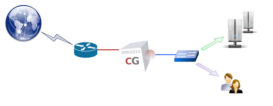
In reverse mode, the CacheGuard appliance acts as a virtual Web server, concealing the real Web servers (referred to as hosts). These cloaked Web servers must then be publicly accessible via the CacheGuard appliance’s external IP address. For example, in the configuration above, the www.example.com name should publicly resolve to 192.168.1.1.
Load Balancing
If multiple hosts are associated with a single website, the total load is distributed among all associated hosts. The CacheGuard appliance continuously monitors host availability, and in the event of a host failure, it temporarily removes that host from the load-balancing pool, thereby maintaining high availability for the website.The default load-balancing method is round-robin, which distributes an equal number of requests to each host. When associating a host with a website, an optional weight may be specified to adjust the load distribution. Furthermore, if the underlying Web application requires that a specific Web client always be served by the same host (to preserve application context), sticky load balancing must be enabled for that website. Sticky connections are based on either an existing HTTP cookie or one inserted by the CacheGuard appliance, which can be configured using the rweb command.
To extend the previous example, the following configuration adds a host with the IP address 10.0.10.12 to the pool of load-balanced hosts and enables round-robin sticky load balancing for the www.example.com website:
- rweb host www.example.com add rweb http 10.0.10.12
- rweb balancer www.example.com robin sticky
- apply
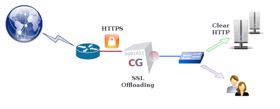
SSL Offloading
To allow a CacheGuard appliance to process (inspect, cache, etc.) Web content within HTTPS (encrypted) traffic, it must first decrypt that traffic to gain unencrypted access to the data. To achieve this, the CacheGuard appliance acts as an SSL terminator for the HTTPS websites it manages. While communication between Web clients and HTTPS websites managed by the appliance is always encrypted, communication between the appliance and hosts may be either encrypted (using HTTPS) or unencrypted (using HTTP).When the HTTP protocol is used for communication with hosts, the CacheGuard appliance performs SSL offloading for those hosts. It is crucial in such configurations to ensure that the unencrypted Web traffic between the appliance and hosts is fully isolated, preventing any unauthorised access. The http keyword in the command "rweb host www.example.com add rweb http 10.0.10.12" specifies the use of SSL offloading for that host. To avoid SSL offloading, replace http with https. Refer to the rweb command manual for further details.
- tls server add myTLSObject
- tls server generate myTLSObject
- rweb site add www.example.com https myTLSObject
- apply